When you click on links to various merchants on this site and make a purchase, this can result in this site earning a commission. Affiliate programs and affiliations include, but are not limited to, the eBay Partner Network.
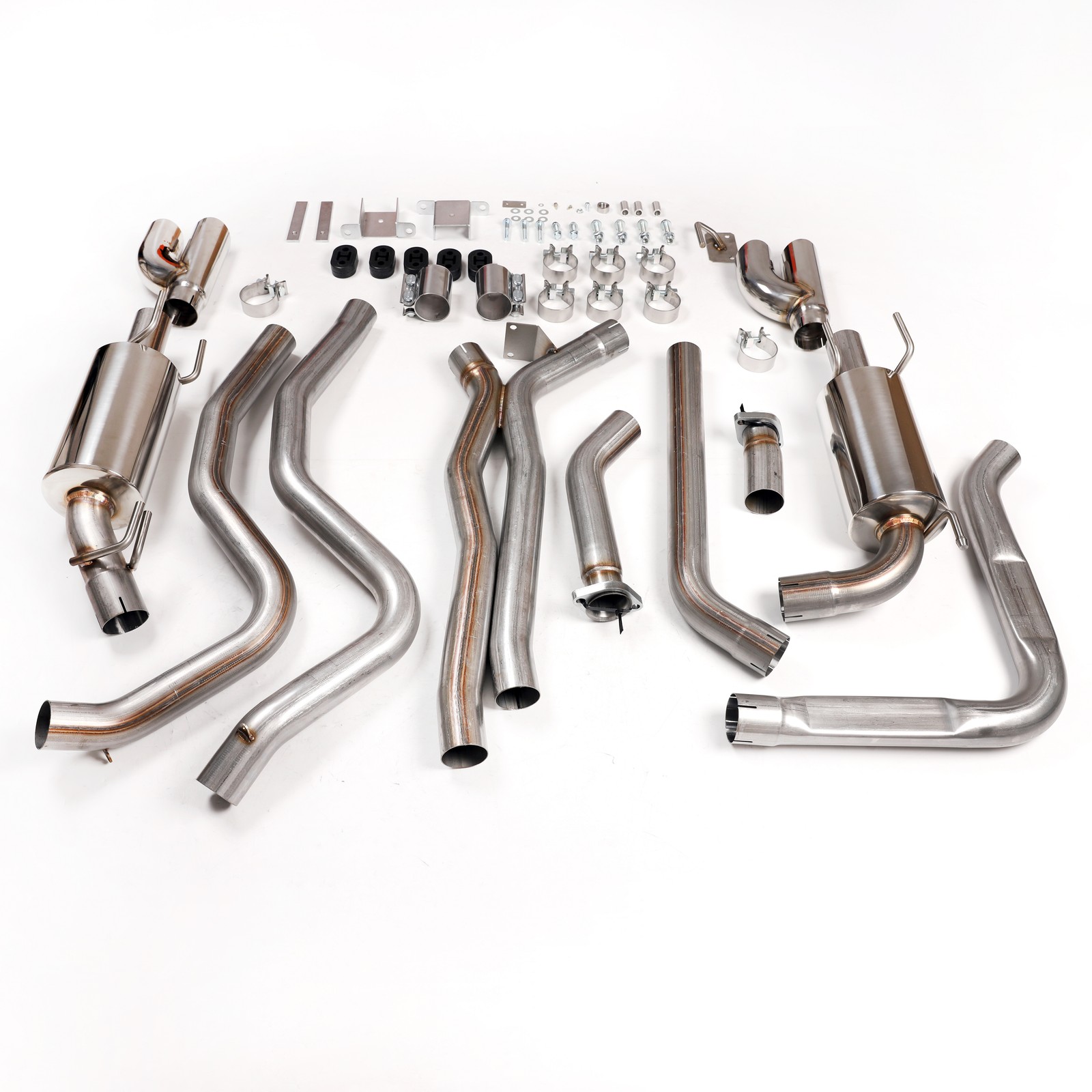
Vehicle Fitment Direct bolt-on cat-back exhaust system designed specifically for 1998-2002 Chevrolet Camaro / Pontiac Firebird 5.7L V8 F-body vehicles. This system is fully 50-state emissions legal for street use and complies with nationwide exhaust regulations. Technical Specifications
- System Type: Cat-Back Exhaust
- Pipe Diameter: 2.5 inch
- Muffler Style: Straight-Through High-Flow Design
- Sound Level: Moderate to Aggressive Exhaust Tone
- Emission Rating: 50-State Legal (Emission Code 5)
- Build Material: Premium 304 Stainless Steel
- Warranty: Manufacturer Limited Lifetime Warranty
Features Crafted from high-grade 304 stainless steel with OEM-quality hardware, this cat-back exhaust system delivers exceptional surface finish, precise factory-style fitment, and long-term durability for daily street driving use. The system connects directly to stock catalytic converter outlets, retaining original emissions equipment and meeting 50-state street-legal requirements. Optimized bend geometry and strategic clamp positioning maximize chassis and ground clearance, preventing scraping and ensuring stable driving adaptability. Built-in crossover structure balances exhaust gas flow for consistent, smooth system operation. Equipped with polished 304 stainless steel mufflers and quad exhaust tips. The tips feature fully adjustable protrusion and rotation, allowing perfect alignment for all Camaro, Firebird Formula, and Trans Am rear bumper configurations. No modification or removal of factory rear axle heat shields is required during installation. The system is fully compatible with stock rear suspension panhard rods and bracing, eliminating the need for aftermarket suspension upgrades. It accommodates all factory and aftermarket driveshafts up to 3.5 inches in diameter. Transmission Compatibility This exhaust system supports a full range of 4th-gen F-body transmissions, including GM TH350, TH400, 700R4, 2004R, 4L60/4L70, 4L80E/4L85E automatic transmissions, as well as factory T56 and aftermarket T56 Magnum manual transmissions. Installation Notes
- 1998-1999 Models: Minor cutting and welding is required to connect the system behind the passenger-side catalytic converter
- 2000-2002 Models: Direct clamp-on installation with no cutting or welding required
- Automotive exhaust installation involves mechanical safety risks. Always work on a clean, dry, level surface with professional vehicle lifting and supporting equipment. Professional installation is highly recommended for users without mechanical experience.
Emission Compliance Statement This exhaust system does not alter, bypass, or disable factory vehicle emissions equipment. It is legally approved for installation and use on emissions-controlled street vehicles, non-emissions-controlled vehicles, and track-only racing vehicles across all 50 U.S. states. California Proposition 65 Warning Automotive exhaust components, stainless steel materials, and installation hardware may contain chemicals known to the State of California to cause cancer and reproductive harm. www.P65Warnings.ca.gov
INSTALLATION:
1.Raise and support the vehicle.
NOTE: On 1998-99 model year vehicles, you must cut the outlet tube of the passenger side catalytic converter about 1.5” past the end of the converter to allow proper removal of the factory Y-pipe assembly.
14.Working from the front side of the axle, feed the right side over-axle tube over the axle and through the space between the upper heat shield and the panhard brace. See Figure 9.
15.Feed the left over-axle tube over the axle in the same manner as the right side over-axle tube. Bring the tab located near the tube outlet to rest against the backside of the corresponding tab attached to the right side over-axle tube. See Figures 10 and 11.
16.Attach the two tabs together with the (x1) supplied 1/4-20 bolt and (x1) lock nut.
17.Raise the front ends of the over-axle tubes up and connect them to the X-pipe outlet legs with the coupler clamps already in position on the X-pipe outlet legs. Orient them in such a way that the nuts on the clamps will be positioned on top of the tubes in the straight-up 12 O’clock position and be facing away from each other (pointed towards the sides of the car) when installed. Tighten the clamp nuts just enough to hold the basic position of the attached components at this time.
18.Attach the (x4) supplied rubber isolators to the supplied rear muffler hanger brackets with the supplied (x4) 1/2 x 1-3/4 flanged head cap screws and (x4) nylon lock nuts. Tighten the nuts enough to remove all slack/clearance between the brackets and the isolators, but not enough to begin to crush the rubber isolators. See Figure 12.
19.Use the supplied (x2) 3/8 x 1-1/4” flanged head cap screws and (x2) rectangular threaded backing bars to attach the muffler hanger bracket assemblies to the left and right frame rails just under the rear bumper. The threaded back-up bars need to be inserted into the interior of the frame rails through the square holes in the sides of the frame. Hold in place with your finger to allow the installation of the bolt that attaches each bracket to the bottom of the frame rails. See Figure 13.
20.Install the stock right side exhaust hanger that was removed from just behind the axle onto the doubled hanger rods attached to the inlet pipe of the right (passenger’s) side muffler. See Figure 14.
21.Place (x1) supplied 2.5” band clamp over the expanded inlet tube of the right side (passenger’s) muffler assembly. Insert the rear hanger rods into the rubber isolators on the right rear hanger bracket just attached under the rear bumper. Lift the muffler up and connect it to the outlet of the right side over axle tube. Do not fully tighten the clamp at this time.
22.Reattach the factory hanger bracket on the muffler inlet pipe to the frame rail with the factory bolts.
23.Attach the supplied left front muffler hanger bracket to the bottom of the left side frame rail, as shown in Figure 15. Use the removed factory fasteners for this purpose.
24.Place (x1) supplied 2.5” band clamp over the expanded inlet tube of the left side (driver’s) muffler assembly and insert the left muffler intermediate tube into the inlet of the muffler.
25.Insert the rear hanger rods on the left (driver’s side) muffler into the rubber isolators on the left rear hanger bracket under the bumper. Lift the muffler up and connect its inlet tube to the outlet of the left side over axle tube using (x1) supplied 2.5” band clamp. Do not fully tighten the band clamp at this time.
26.Couple the hanger rod attached to the rear of the left side muffler to the supplied hanger bracket attached to the left frame rail with the remaining (x1) supplied rubber isolator.
27.Place the remaining (x2) supplied 2.5” band clamps over the tip inlets and install the tip assemblies onto the muffler outlets. The tips should be installed so that the compound angle cut on their ends follow the angled contour of the bumper.
28.Adjust all system components and tighten the clamps. A few tips to remember to accomplish optimized fitment/clearances are as follows:
- Begin by tightening all clamps just enough to remove all “slop” from the system, but still allow the rotation of each tube to be adjusted without major force being required.
- The X-pipe assembly should lie flat in the tunnel when the installation is complete. ·
- Ensure the header collector adapter tubes are rotated over far enough for the O2 sensors to clear the floor.
- Pay special attention to the clearances obtained where the over-axle tubes route over the axle and past the panhard brace as the fitment/clearance constraints are greatest in this area.
- The amount of tip assembly protrusion beyond the rear bumper can be adjusted to suit your individual taste…tucking them in tight, or pulling them out to be more noticeable is completely up to each user.
- Perfect rotational alignment of the tip assemblies with each other can most easily be accomplished by laying a long piece of metal tubing or flat bar across the bottoms of the tips before tightening the clamps.
29.On 1998 and 1999 model year vehicles only, locate the best position for the rear O2 sensor in the tube behind the passenger side catalytic converter and drill a 3/4“ hole in that location. De-bur the hole and weld the included O2 sensor bung on the tube centered over the hole. Transfer the O2 sensor from the factory Y-pipe to the new installed bung and connect the sensor to the vehicle wiring harness. Disconnect the negative battery before performing any welding.